Moving a treadmill is never easy. But have no fears, we’re here to make it as easy as it can be. With a quick guide on how to disassemble a Nordictrack x9i treadmill for moving. Including the tools needed and image showing the locations of all the screws. So let’s get to work.
* All images are taken directly from the Nordictrack x9i owners manual.
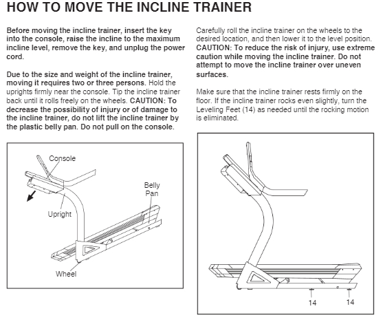
How to Roll / Move the Nordictrack x9i treadmill
Below is an image showing the proper way of moving/rolling the Nordictrack x9i treadmill.
A Step by Step Guide on How to Disassemble a Nordictrack x9i Treadmill
Tools You Will Need
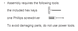
- 1 Hex Head Scree Driver
- 1 Phillips Head Screwdriver
* To avoid damaging parts, do not use power tools.
Disassembly Instructions
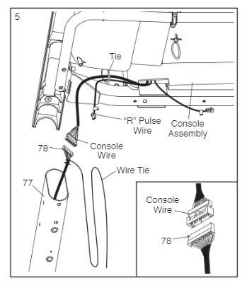
Step 1. Removing Left & Right Bottom Covers
* This step involves adjusting the incline and plugging/unplugging in the treadmill. Please read and be careful.
For this step you are going to start with the treadmill plugged in and powered on. Then you need to turn the incline to 40%. Let the treadmill adjust to the 40% incline and once it does, unplug the power cord. This will allow you access to the left and right bottom covers (3).
Now from the inside of each cover you will remove 3 screws (1) holding the two sides together. Remove both pieces from both the left and right side of the treadmill.
Once you have removed the two covers, plug the treadmill back in and lower to a flat 0% incline. Then turn the machine off and remove the power cord.
Step 2. Removing back console cover
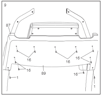
Use the screwdriver to remove 9 machine screws (16) and 2 screws (1) from the back of the main console. This is 11 screws in total.
Make sure to have something safe to put all of these screws in once you remove them.
Step 3. Remove left hand rail assembly
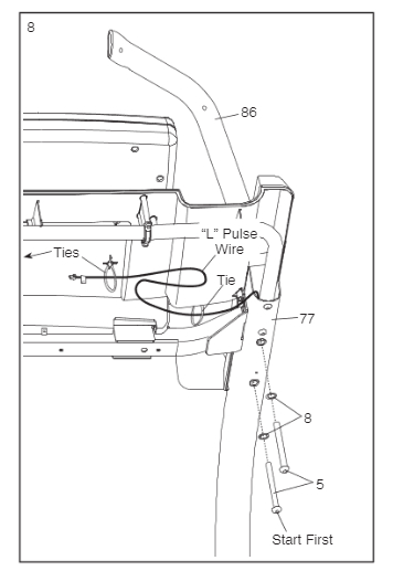
First you are going to disconnect the “L pulse wire” in the diagram. (you can disconnect the right side wire at this point too.)
Then remove two 5 ½ inch screws and washers from the top left of the frame that are connecting the left hand rail assembly (86).
Step 4. Remove right hand rail assembly
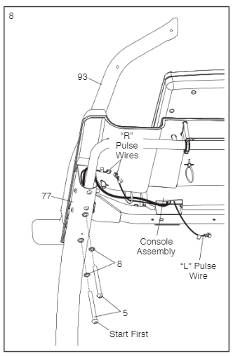
Disconnect the “R Pulse Wire” (if you haven’t already).
Then remove two 5 ½ inch screws and washers from the top right of the frame that are connecting the right hand rail assembly (86).
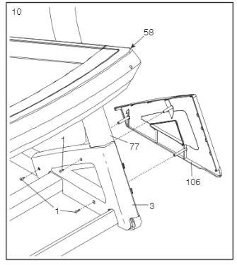
Step 5. Unscrewing the console assembly
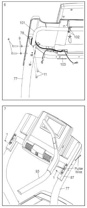
To disconnect the console assembly you will start on the right side. By removing 2 screws (4) and washers (9) from the right frame rail (77). Then remove 2 more screws (11) from under the right frame rail (77).
Repeat this process on the left side.
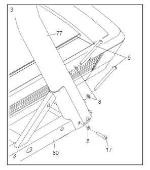
Step 6. Disconnecting the console assembly wiring
* For step 6 you would have someone to help you hold the console assembly once you unscrew it, and for helping hold it while disconnecting the console wire. Running though the right frame rail.
Have someone help you slowly lift the console assembly bars out of the left and right (77) side rails a few inches. Just enough to expose the “console wire connection” (do not let it fall into the frame yet). Now disconnect the “console wire” and place the console assembly someplace safe.
Bonus step: Create a guide wire for pulling the cable back through on assembly.
Before letting the “console wire” fall into the frame, tie a string around the main connection. Give the string a bunch of lead (enough to run the full length of the rail plus some. And then tape that end, not attached to cable to the top of the side rail so it doesn’t fall through. After the next step, and we pull the cable through you will tape the other end to the bottom. So when you need to run the cable back through to set it up, you have a guide wire. Just tie the bottom end back to the cable and pull it through.
Step 7. Disconnect left and right side rails
* The main cable runs down the right hand rail. Be careful when disconnecting.
Unscrew one smaller screw (17) and washer (8) from the side connecting the base (80) to the right rail (77). And then Remove 2 main bolts (5) and washers (8) from the back of the right side rail.
Repeat for the left side.
Step 8. Remove cable from the right frame rail
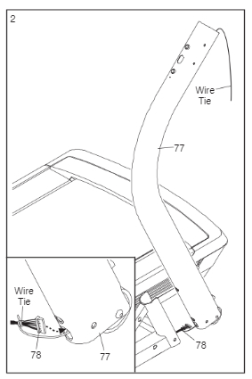
For the last step you will run the main cable down and out of the right frame rail (77). Be Careful when removing the cable.
This is where I recommend resting a guide wire as shown in the image for setup.
Conclusion
Moving a NordicTrack x9i treadmill can be a breeze with our disassembly guide. To ensure a smooth relocation, you’ll need just two tools: a Hex Head Screwdriver and a Phillips Head Screwdriver (avoid power tools to prevent damage). Here’s a concise summary of the steps:
1: Removing Left & Right Bottom Covers Adjust the incline to 40%, unplug the power cord, and remove 3 screws from inside each cover. Remove both covers, then lower the incline to 0% and turn off the treadmill.
2: Removing Back Console Cover Unscrew 9 machine screws and 2 screws from the back of the main console. Keep these screws safe.
3: Remove Left Hand Rail Assembly Disconnect the “L Pulse Wire,” then remove two 5 ½ inch screws and washers from the top left of the frame connecting the left hand rail assembly.
4: Remove Right Hand Rail Assembly Disconnect the “R Pulse Wire,” then remove two 5 ½ inch screws and washers from the top right of the frame connecting the right hand rail assembly.
5: Unscrewing the Console Assembly Remove screws and washers from both frame rails (77) to disconnect the console assembly.
6: Disconnecting the Console Assembly Wiring Lift the console assembly bars a few inches to expose the “console wire connection” and disconnect it. Secure the console assembly safely.
Bonus Step: Create a Guide Wire (for reassembly) Tie a string around the main connection of the console wire and tape one end to the top of the side rail. This will serve as a guide wire for reassembly.
Step 7: Disconnect Left and Right Side Rails Unscrew smaller screw and washer connecting the base (80) to each side rail. Remove 2 main bolts and washers from the back of each side rail.
Step 8: Remove Cable from the Right Frame Rail Carefully run the main cable down and out of the right frame rail. Use the guide wire if needed for setup.
Following these steps, you’ll be well-prepared to move your NordicTrack x9i treadmill without hassle.