The NordicTrack Commercial Treadmill 2450 is a fitness enthusiast’s dream machine, offering a powerful platform for intense workouts within the comfort of your own home. However, there comes a time when even the most reliable fitness equipment requires maintenance or relocation. Whether you’re looking to move your treadmill to a new location, perform repairs, or simply clean hard-to-reach areas, disassembling it properly is a crucial step. In this comprehensive guide, we’ll take you through the step-by-step process of how to disassemble the NordicTrack Commercial Treadmill 2450.
By following these instructions carefully, you’ll not only ensure a smooth disassembly but also gain valuable insights into the inner workings of this exceptional fitness equipment. Whether you’re a seasoned DIY enthusiast or a first-time treadmill owner, this guide is designed to simplify the disassembly process and help you keep your treadmill in peak condition.
A Step by Step Guide on How to Disassemble The Nordictrack Commercial Treadmill 2450

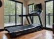
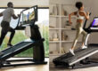
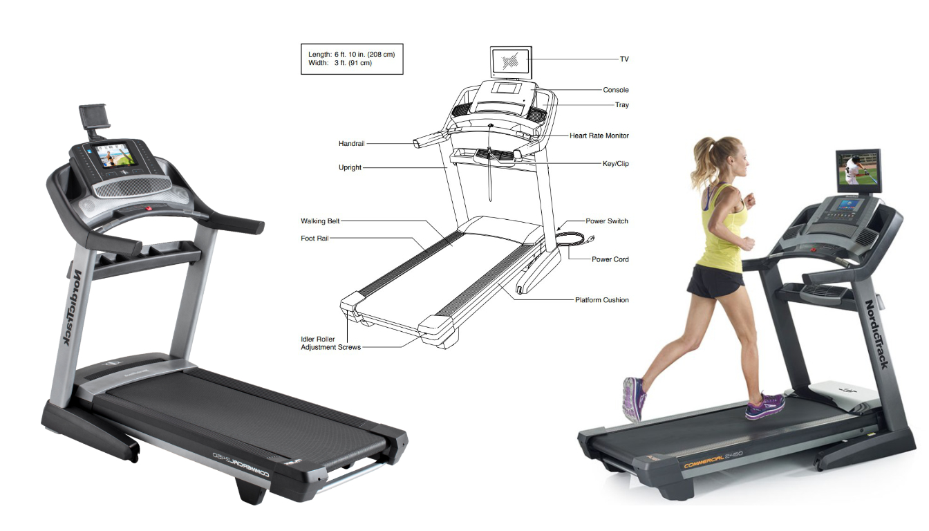
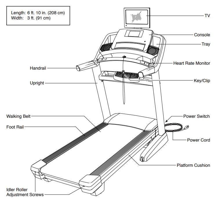
It should be noted that there are a few different versions of the Commercial Treadmill 2450 available, some with the display located in the main console, others with the display on top like shown below. The main disassembly is the same for all of these models minus the top mounted display. So if you have a newer model with the display in the console, after reviewing the tools needed you can skip to step 5.
Before we dive into the nitty-gritty of disassembly, it’s essential to gather the necessary tools and prepare your workspace. So, let’s roll up our sleeves and embark on this journey to uncover the secrets of your NordicTrack Commercial Treadmill 2450!
Tools Needed
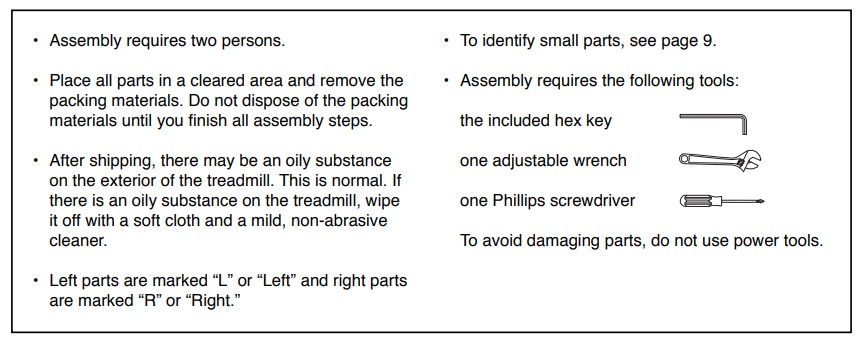
Disassembly requires the following tools:
- the included hex key
- one adjustable wrench
- one Phillips screwdriver
To avoid damaging parts, do not use power tools.
Step by Step Disassembly Guide
The provided text appears to be assembly instructions for a piece of equipment. To reverse these instructions into disassembly instructions, we need to describe the steps to take apart the equipment. Here are the disassembly instructions, with images taken directly from the product manuals which you can view by clicking here.
Disassembly Instructions:

Before you get started, make sure you have unplugged the power supply to the treadmill, along with the coaxel cable at the bottom if you had it connected.

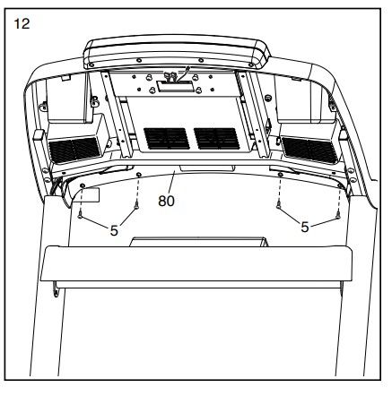
1. Remove the Lower TV Bracket Cover: Unscrew and remove the four #8 x 3/4″ Screws (5) that secure the Lower TV Bracket Cover (97) to the console assembly. Be careful not to overtighten the Screws.
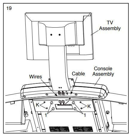
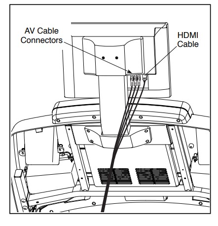
2. Separate the TV Assembly & Disconnect Wires and Coaxial Cable: Unscrew and remove the four 5/16″ x 3/4″ Screws (1) that attach the TV assembly to the console assembly. Be careful not to pinch the wires during this process. Disconnect the wires and the coaxial cable on the TV assembly from the wires and the coaxial cable on the console assembly.

3. Detach the Upper TV Bracket Cover: Unfasten and detach the Upper TV Bracket Cover (103) from the TV Bracket (131) by removing the two #8 x 3/4″ Screws (5).

4. Remove TV Bracket from TV & Pull Wires and Cable through TV Bracket: Use the four M4 x 12mm Screws (130) saved from step 16 to detach the TV Bracket (131) from the TV (102). Carefully pull the wires and the coaxial cable from the TV (102) through the hole in the TV Bracket (131) as shown in drawing 17b.

5. Remove the Storage Latch: It may help to have someone helping you with these next two steps. Start by lifting the deck, then detach the Storage Latch (56) by unscrewing the 5/16″ x 2 1/4″ Bolt (4) and 5/16″ Nut (9).

6. Detach the Storage Latch from Upright: Unscrew the 5/16″ x 1 3/4″ Bolt (3) and 5/16″ Nut (9) securing the lower end of the Storage Latch (56) to the bracket on the base of the Upright (84). Remove and discard the tie (H).

7. Remove Handrail Covers: Unscrew and remove the four #8 x 3/4″ Truss Head Screws (24) attaching the Left Handrail Top Cover (73) to the left Handrail (74), the Left Handrail Bottom Cover (75), and the Left Handrail Top Cover. Next detach the Right Handrail Top and Bottom Covers (81, 82) from the right Handrail (74) by unscrewing and removing the four #8 x 3/4″ Truss Head Screws (24).
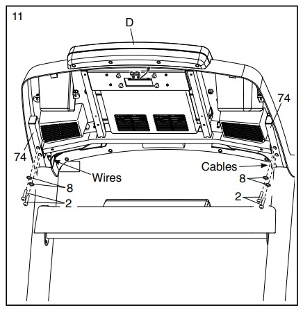
8. Detach Console Assembly: Before starting this next section, make sure you have someone to help hold the console. Once you unscrew the console it will still have a cable that will needed to be disconnected, so don’t pull the console too far from the base before the nest step.
Start by unscrewing the four bottom screws (5) from the lower section of the console (80). Next we will remove the main console Unscrew and remove the four 5/16″ x 2″ Screws (2) and four 5/16″ Star Washers (8) securing the console assembly (D) to the Handrails (74). Be careful not to pinch the wires and cables during this process. Insert the wires and cables upward into the console assembly (D).
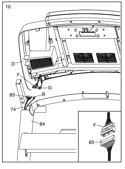
9: Disconnect Console Cables: Once you have the console disconnected, lift it slightly from the base to expose the cable connection. Then disconnect the cables.

10. Detach Pulse Crossbar: Remove the Pulse Crossbar (80) by unscrewing and removing the two #10 x 3/4″ Screws (6), two 5/16″ Star Washers (8), and two of the 5/16″ x 2″ Screws (2) that were previously removed in step 3. Then, tighten the other two 5/16″ x 2″ Screws (2).
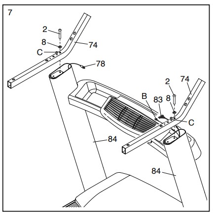
11. Remove Left & Right Handrails: Unscrew and remove the two Screws (2) securing the left and right handrails (74) to the upright supports (84).
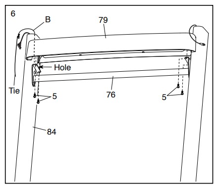
12. Remove Tray: Remove the Tray (79) from the Upright Crossbar (76) held in place by four screws (5).

13. Removing the Upright Cross Bar: After the tray has been removed, we will remove the upright crossbar (76). These are held in place with four screws (1). Remove these then the it should come free from the uprights (84).
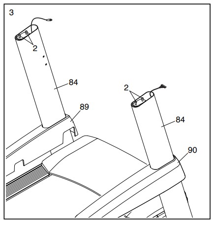
14. Remove Upright Covers: Slide off the Right Upright Cover (90) from the right Upright (84) and the Left Upright Cover (89) from the left Upright (84).Unplug the Power Cord: Ensure the power cord is unplugged from the equipment.

15. Detach Extension Legs: Unscrew and remove the Right Extension Leg (91) from the right Upright (84) and the Left Extension Leg from the left Upright (84) using two 5/16″ x 3/4″ Screws (1) for each leg.
Now, you have successfully disassembled the equipment following these steps in reverse order.
Closing Thoughts – Step by Step Guide to Disassemble The NordicTrack Commercial Treadmill 2450
In conclusion, disassembling the NordicTrack Commercial Treadmill 2450 is a manageable task when approached with the right knowledge and careful attention. By following the steps outlined in this guide, you can confidently disassemble your treadmill for maintenance, repairs, or relocation. Remember to keep all the components organized, use appropriate tools, and exercise patience throughout the process. Taking the time to disassemble and reassemble your treadmill correctly ensures its longevity and continued exceptional performance. With your newfound understanding of the NordicTrack Commercial Treadmill 2450’s inner workings, you’re better equipped to keep this fitness powerhouse at its best, helping you reach your fitness goals for years to come.